|
|
|
Who's Online
There currently are 5787 guests online. |
|
Categories
|
|
Information
|
|
Featured Product
|
|
|
 |
|
|
There are currently no product reviews.
 ;
exactly as they say. Within 24 hours the link to the pages and offcourse it was the right service manual. Super and thanks
 ;
The manual was exact the thing that was promised. My old car stereo is working again thanks to the information supplied.
;
I PURHASED THIS PRODUCT BECAUSE I WAS HAVING PROBLEMS WITH MY CDR20 HARMAN KARDON RECORDER. WHICH I PURCHASED NEW 12 YEARS AGO. AFTER REVIEWING THE MANUAL, I WAS ABLE TO ADJUST THE TENSIONER IN THE SYSTEM. WORKS LIKE A CHAMP!.
SAVED ME AT LEAST 100.00 WHICH WAS WHAT A SERVICE REPAIR STATION WANTED. GREAT MANUAL EASY TO READ. SPECIALLY AFTER I PRINTED THE PAGES WHICH DEALT WITH MY RECORDER. THANKS A LOT!!!!!!!!
;
You can fully trust on this one!
All the schematics are very crear an in one piece per page
;
I have never bought a service manual which is as competely readable as this althogh it was a scanned pdf. Thank you for this succesful manual also cheaper than other sites.
NOTE ON BEFORE STARTING REPAIR
1. Forced discharge of electrolytic capacitor of power supply block
When repair is going to be attempted in the set that uses relay circuit in the power supply block, electric potential is kept charged across the electrolytic capacitors (C101, 102) even though AC power cord is removed. If repair is attempted in this condition, secondary defect can occur. In order to prevent the secondary trouble, perform the following measures before starting repair work.
Discharge procedure
1 Remove the AC power cord. 2 Connect a discharging resistor at an end of lead wire that has clips at both ends. Connect the other end of the lead wire to metal chassis. 3 Contact the other end of the discharging resistor to the positive (+) side (+VH) of C101. (For two seconds) 4 Contact the same end of the discharging resistor as step 3 to the negative (-) side (-VH) of C102 in the same way. (For two seconds) 5 Check that voltage across C101 and C102 has decreased to 1 V or less using a multimeter or an oscilloscope.
MAIN C.B D101
3 C101 C102
4
2
2
Select a discharging resistor referring to the following table. Charging voltage (V) (C101, 102) 25-48 49-140 Discharging resistor (�) 100 220 Rated power (W) 3 5 Parts number 87-A00-247-090 87-A00-232-090
Fig-1
Note: The reference numbers (C101, C102) of the electrolytic capacitors can change depending on the models. Be sure to check the reference numbers of the charging capacitors on schematic diagram before starting the discharging work.
2. Check items before exchanging the MICROCOMPUTER
Be sure to check the following items before exchanging the MICROCOMPUTER. Exchange the MICROCOMPUTER after confirming that the MICROCOMPUTER is surely defective.
2-1. Regarding the HOLD terminal of the MICROCOMPUTER
When the HOLD terminal (INPUT) of the MICROCOMPUTER is �H�, the MICROCOMPUTER is judged to be operating correctly. When this terminal is �L�, the main power cannot be turned on. Therefore, be sure to check the terminal voltage of the HOLD terminal before exchange. When the MICROCOMPUTER is not defective, the HOLD terminal can also go �L� when the POWER AMPLIFIER has any abnormalities that triggers the abnormality detection circuit on the MAIN C. B. that sets the HOLD terminal to �L�.
� Good or no good judgement of the MICROCOMPUTER
1 Turn on the AC main power. 2 Confirm that the main power is turned on and the HOLD terminal of the MICROCOMPUTER keeps the �H� level or not. 3 When the HOLD terminal is �L� level, the abnormality detection circuit is judged to be working correctly and the MICROCOMPUTER is judged to be good.
�4�
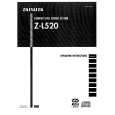 $4.99 ZL520 AIWA
Owner's Manual Complete owner's manual in digital format. The manual will be available for download as PDF file aft…
|
|
|
> |
|