|
|
|
Who's Online
There currently are 5684 guests online. |
|
Categories
|
|
Information
|
|
Featured Product
|
|
|
 |
|
|
There are currently no product reviews.
 ;
Excellent quality, very quick download turnaround, will definately use again.
 ;
This is a awesome quality scan of the original Service Manual for Technics 8099.
Contains the circuit diagram, PCB layout, adjust/tune instructions as well.
Since this is my first buy here, i'm really glad! This site do works as intended/described, it's definitely not scam!
Мои рекомендации! Все мануалы настоящие!
;
Good Quality of the File.
You get the normal manual is incudet.
;
Very nice and real Service Manual, I didn't thought it actually exist in the real world at all.
;
VERY NICE FOR COURTESY AND PRECISION!.
tHE SITE IS VERY IMPORTANT FOR ALL DEVICES
vERY GOOD
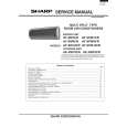
ADJUSTMENT (TUNER / DECK / FRONT)
A MAIN C.B
9 8
9 4 2 5 3
L802 L801 TP3 IC80124 TP2 (CLK) R815 TP4 L942
TC943
L941
TC941
L953 4
L952
TP1 FFE831 (VT)
GND TP8 (LCH) TP9 (RCH) 3 5 7 8 9 IC601
1
2
4
6
< TUNER SECTION >
1. Clock Frequency Check Settings : � Test point : TP2 (CLK) Method : Set to MW 1602kHz and check that the test point is 2052kHz ± 45Hz. 2. MW VT Adjustment Settings : � Test point : TP1 (VT) � Adjustment location : L953 Method : Set to MW 1710kHz and adjust L953 so that the test point become 8.3V ± 0.05V. Then set to MW 530kHz and check that the test point is more than 0.3V. 3. MW Tracking Adjustment Settings : � Test point : TP8 (Lch), TP9 (Rch) � Adjustment location : L952............................... 603kHz TC941............................ 1404kHz Method : Set up TC941 to center before adjustment. Adjust L952 so that level at 603kHz become maximum. Then adjust TC941 so that the level at 1404kHz becomes maximum. 4. SW VT Adjustment Settings : � Test point : TP1 (VT) � Adjustment location : L942 Method : Set to SW 17.9MHz and adjust L942 so that the test point becomes 8.5V ± 0.2V. Then set to SW 5.9MHz and check that the test point is more than 0.3V. 5. SW Tracking Adjustment Settings : � Test point : TP8 (Lch), TP9 (Rch) � Ajustment location : L941............................... 5.9MHz TC943.............................17.9MHz Method : Set up TC943 to center before adjustment. Adjust L941 so that level at 5.9MHz becomes maximum. Then adjust TC943 so that the level at 17.9MHz becomes maximum. 6. FM VT Check Settings : � Test point : TP1 (VT) Method : Set to FM 108.0MHz and check that the test point is less than 8.0V. Then set to FM 87.5MHz and check that the test point is more than 0.5V. 7. FM Tracking Check Settings : � Test point : TP8 (Lch), TP9 (Rch) Method : Set to FM 98.0MHz and check that the test point is less than 9.0dBµV. 8. AM IF Adjustment Settings : � Test point : TP8 (Lch), TP9 (Rch) � Adjustment location : L802............450kHz 9. DC Balance / Mono Distortion Adjustment Settings : � Test point : TP3, TP4 (DC Balance) TP8 (Lch), TP9 (Rch) � Adjustment location : L801 � Input level : 60dBµV Method : Set to FM 98.0MHz and adjust L801 so that the voltage between TP3 and TP4 becomes 0V ± 0.3V. Next, check that the distortion is minimum.
� 32 �
|
|
|
> |
|