|
|
|
Who's Online
There currently are 6040 guests online. |
|
Categories
|
|
Information
|
|
Featured Product
|
|
|
 |
|
|
There are currently no product reviews.
 ;
good and ok, very nice , good and ok, very nice, good and ok, very nice
;
Super manual it contains all the things you need to service your Marantz 2100.
;
A very easy to understand and use manual. Well worth the money.
 ;
Very good information with clear drawings. Thanks!
;
The ease of this purchase was a good start. The content of this manual was exactly all I needed to retore my Tandberg 64.
All of the mechanical and electrical information is contained in the manual and the quality of the document makes reading the data easy.
The exerience with the resource has made this my prime source for technical data.
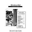
B FRONT C.B
18
D981
<HA>
D984
<HR>
FL901
TP11 IC901 L951
3 0 1
+ C913
GND TP11 (KEY-SCAN) (GND) < CR NETWORK FILTER > 10µF 10µF 1k� 1SS133 1k� 0.1µF 47k� TO FREQUENCY COUNTER
D DECK C.B<HA>
SFR1 12
D DECK C.B<HR>
SFR1 12
DECK�1 P HEAD<HA> DECK�2 R/P/E HEAD
FWD
13
DECK�1 P HEAD<HR>
FWD
13
REV
13
REV
13
< DECK SECTION >
12. Tape Speed Adjustment (DECK 2) Settings : � Test tape : TTA�100 � Test point : TP8(Lch), TP9(Rch) � Adjustment location : SFR1 Method : Play back the test tape and adjust SFR1 so that the frequency counter reads 3000Hz ± 5Hz (FWD) and FWD SPEED ± 45Hz (REV). 13. Head Azimuth Adjustment (DECK 1, DECK 2) Settings : � Test tape : TTA�330 � Test point : TP8(Lch), TP9(Rch) � Adjustment location : Azimuth adjustment screw Method : Play back (FWD) the 8kHz signal of the test tape and adjust screw so that the output becomes maximum. Next, perform on REV PLAY mode. 14. PB Frequency Response Check (DECK 1, DECK 2) Settings : � Test tape : TTA�330 � Test point :TP8(Lch), TP9(Rch) Method : Play back the 315Hz and 8kHz signals of the test tape and check that the output ratio of the 8kHz signal with respect to that of the 315Hz signal is within 5.0dB. 15. PB Sensitivity Check (DECK 1, DECK 2) Settings : � Test tape : TTA�200 � Test point : TP8(Lch), TP9(Rch) Method : Play back the test tape and check that the output level of the test point is 110mV ± 3.0dB. 16. REC/PB Frequency Response Adjustment (DECK 2) Settings : � Test tape : TTA�602 � Test point : TP8(Lch), TP9(Rch) � Input signal : 1kHz / 8kHz (LINE IN) � Adjustment location : SFR451 (Lch) SFR452 (Rch) Method : Apply a 1kHz signal and REC mode. Then adjust OSC attenuator so that the output level at the TP8, TP9 becomes -20VU (-26dBV). Record and play back the 1kHz and 8kHz signals and adjust SFRs so that the output of the 8kHz signals becomes 1.5dB ± 0.5dB with respect to that of the 1kHz signal. 17. REC/PB Sensitivity Check (DECK 2) Settings : � Test tape : TTA�602 � Test point : TP8(Lch), TP9(Rch) � Input signal : 1kHz (LINE IN) Method : Apply a 1kHz signal and REC mode. Then adjust OSC attenuator so that the output level at TP8, TP9 becomes 0VU (-6dBV). Record and play back the 1kHz signals and check that the output is -1dB ± 3.5dB.
< FRONT SECTION >
18. µ-con OSC Adjustment Settings : � Test point : TP11(KEY-SCAN), GND � Adjustment location : L951 Method : Connect a frequency counter across TP11 and GND via a CR network filter. Then adjust L951 so that the test point becomes 184.94Hz ± 0.18Hz.
� 21 �
|
|
|
> |
|