|
|
|
Who's Online
There currently are 5876 guests online. |
|
Categories
|
|
Information
|
|
Featured Product
|
|
|
 |
|
|
There are currently no product reviews.
 ;
Hi - happy with what I received but not quite what I wanted - my fault I assumed that service manual would also include operational instructions which is what I needed - all I needed to know was how to turn the radio - thanks
;
this Manual very important when i buy this Manual i already fix the trouble of my Camera..... thanks keep up the good work.!
 ;
This service manual helped me to repair my PIONEER. Iam very satisfied, that I found it here.
Even the price of manual was not so high that person would not be able to spend a few money.
But that is very worth spent money. Thanks
;
Excellent quality service manual. Quick processing, fair prices. Love to do business again. Thank you!!!
;
Excellent service manual, the only known point of note is the alignment of improvability scanned pages within the pdf page. The resolution is good.
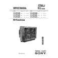
NOTE
1. Forced
When across
ON
BEFORE
STARTING
of electrolytic
REPAIR
capacitor
discharge
repair is going
of power
relay circuit
supply
block
supply block, If repair electric potential is kept charged the
to be attempted capacitors
in the set that uses 102) even though
in the power cord
the electrolytic defect to prevent
(Cl 01,
AC power
is removed.
is attempted
in this condition,
secondary In order
can occur. the secondary trouble, perform the following measures before starting repair work.
Discharge
Remove Connect hasclips lead wire
procedure
the AC power a discharging at bothends. to metal the other (+) side the same cord. resistor Connector chassis. end (+VH) end of the discharging of C101. (For resistor two to the at an end of lead theotherend wire of the that
I I
II
II
MAIN C.B
Contact positive Contact
seconds) as step
of the discharging (-VH) of C102
resistor
@) to the negative way. Check (For that two
(-) side
in the same
seconds) across CIO1 and C102 has decreased 6 L @
voltage using
1 V or less
a multimeter
or an oscilloscope.
Select
a discharging voltage
resistor
(V)
referring
Discharging
to the following
table.
Fig-1
Charging
Rated power (W) (Clol,
25-48
Parts
number
102)
resistor 100
(Q)
3 5 C102) of the electrolytic on schematic capacitors diagram
87-AOO-247-090 87-AOO-232-090 can change before depending on the models. work. Be sure to check the
49-140 Note: The reference numbers
220 (C101,
reference
numbers
of the charging
capacitor
starting
the discharging
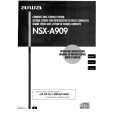
2.
Check
Be sure confirming
items
to check that
before
exchanging
items before
the
MICROCOMPUTER
the MICROCOMPUTER. Exchange the MICROCOMPUTER after
the following
exchanging is surely
the MICROCOMPUTER
defective.
2-1.
Regarding
When
the HOLD
terminal this
terminal
(INPUT) is �L�,
of the MICROCOMPUTER
of the MICROCOMPUTER the main power cannot is �H�, be turned the MICROCOMPUTER on. Therefore, be sure is judged to check to be operating voltage of
the HOLD When terminal
correctly. the HOLD When
terminal before
the terminal
exchange. is not defective, the abnormality the HOLD circuit terminal can also go �L� when sets the POWER AMPLIFIER to �L�. has any
the MICROCOMPUTER that triggers
abnormalities
detection
on the MAIN
C. B. that
the HOLD
terminal
q
Good
or no good
judgment
power. power
of the MICROCOMPUTER
Turn
on the AC main that the main
Confirm not. When
is turned
on and the HOLD
terminal
of the MICROCOMPUTER
keeps
the �H
level
or
the HOLD
terminal
is �L� level,
the abnormality
detection
circuit
is judged
to be working
correctly
and the
MICROCOMPUTER
is judged
to be good.
In some MICROCOMF a I +
models,
it is PIN
@.
8= 8
OVER
LOAD
DET
POWER
AMP
I
DC DET POWER AMP ,~
-? depending �.�
upon
microprocessor.
t
.�.
�.
I J
1 11==��
I-.
i
-.-.
Ill
-._.
_._..
Fig-2-1
-4-
 $4.99 NSXA909 AIWA
Owner's Manual Complete owner's manual in digital format. The manual will be available for download as PDF file aft…
|
|
|
> |
|