|
|
|
Who's Online
There currently are 6043 guests online. |
|
Categories
|
|
Information
|
|
Featured Product
|
|
|
 |
|
|
There are currently no product reviews.
 ;
Good service manual,exploded view,adjusment and test point locations,head alignment,mechanical checks and adjusments,all perfect.
;
Block diagram,play rec block diagram,adjusments, it's a very good well done repair manual.
;
Very clear copy of the philips service manual. Fast delivery. Thank you very much
;
Excellent manual, detailed, very useful! Exactly what I needed, I'd recommend it to all who need it. Although images are scanned easily readable and explicit. A valuable tool product at a price more than modest, take it with confidence and you will not regret it!
;
Clear and complete service manual. Easy now to restore my old Kenwood KD-1500.
Thanks a lot.
I C LA9241ML , PinNo.
1 Pin Name FIN2 FIN I 3 141 I/o I Description Pinto which external picknpphoto diode isconnected. RFsignal iscreated byadding with the FIN1 pin signal. FE signal is created by subtracting from the FIN1 pin signal.
121
Pin to which external pickup photo diode is connected. Pin to which external pickup photo diode is connected. TE signrd is created by
I
E F TB TE-
I
I
subtracting from the F pin signal.
Pin to which external pickup photo diode is connected. DC component of the TE signal is input. Pin to which external resistor setting the TE signal gain is connected between the TE pin. pass filter then input. I o TE signal output pin.
H--=-R
191
10 11 SCI TH TA TD-
TES �Track Error Sense� comparator input pin. TE signal is passed through a band-
Shock detection signal input pin. Tracking gain time constant setting pin. TA amplifier output pin. Pin to which external tracking phase compensation constants are connected between the TD and VR pins.
I I
13 14
I I
TD JP TO
Tracking phase compensation setting pin. Tracking jump signal (kick pulse) amplitude setting pin. Tracking control signal output pin. Focusing control signal output pin,
R-t---+
I
18 I FA I
Pin to which external focusing phase compensation constants are connected between the FD and FA pins. Pin to which external focusing phase compensation constants are connected between the FD� and FA� pins.
I
19
I
FA� FE
1
0
Pin to which external focusing phase compensation constants are connected between the FA and FE pins. FE signal output pin. Pin to which external FE signal gain setting resistor is connected between the FE pin. Analog signal GND,
1
�
No connection. Single ended output of the CV+ and CV� pin input signal. Pin to which external spindle gain setting resistor in 12 cm mode is connected. Pin to which external spindle phase compensation constants are connected together with SPD pin.
I
24 25 26 27 28 29 I I I
SP SPG sPSPD SLEQ SLD
o I 1
I
I
Spindle control signal output pin. Pin to which external sled phase compensation constants are connected. Sled control signal output pin. Sled advance signal input pin from microprocessor. Tracking jump signal input pin from DSP. Tracking gain control signal input from DSP. Low gain when TGL = H. I
35
I
TOFF
Tracking off control signal input pin from DSP. Off when TOFF = H.
34
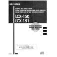 $4.99 LCX151 AIWA
Owner's Manual Complete owner's manual in digital format. The manual will be available for download as PDF file aft…
|
|
|
> |
|