|
|
|
Who's Online
There currently are 6040 guests and
3 members online. |
|
Categories
|
|
Information
|
|
Featured Product
|
|
|
 |
|
|
There are currently no product reviews.
 ;
This is exactly the thing you need to service this box. The manual is complete and the quality of the scan is good. I recommend this!
;
The delivery of this manual was very fast, less than 8 hours. The manual is very clear and concise, and helped a great deal in the repair and final setup of the Hitachi HMA-G2 Amplifier.
;
Great service. The manual was exactly what I was looking for: schematic + layout. I managed to fix the player. Highly recommended!
 ;
At $5,00 certainly good bang for your buck. Includes electric schematics as well as exploded parts view + parts list for reordering. Unfortunately no details on the PCB contents or working, but then again, this is not overly complex. Best bonus: this manual does contain the heavily searched for LED error codes as well as descriptions for test operation. Haven't gotten around to fixing the machine yet, one thing the manual won't do for you is getting it out of the kitchen assembly :-(
;
It`s not your fault tear down is rather incomplete. It doesn`t have complete instructions as to deconstruction for repair.
IC DESCRIPTION IC, UPD780228GF
Pin No. 1 2 3 4 5 6 7 8 9 10 11 12 13 14-16 17 18 19 20, 21 22 23 24 25 26 27 28 29 30 31 32 33 34 35 36 37 38 39 40 41 42 43 Pin Name
________________
I/O O O O I O O O O O O � I O � � � � � O O O I I O I I � O O O I O O � � � � � I I
Description Scan output to diode input (Active �L�). Tuner PLL chip enable output. Sound CTRL, PLL, DOLBY PROLOGIC or DSP, AC-3 VOL, GEQ. Data output.
__________________
Pin No. 44 45 46 47, 48 49 50 51 52 53-64 65 66, 67 68 69-73 74 75 76-78 79 80 81-89 90-100
Pin Name I-SYNC-DET/I-RDS-SIG I-JOG2 I-FU-JOG1 I-KEY2, I-KEY1 I-MIC AVSS O-STB-31 POWER-LED P35-P24 P23/I-AM10K P22/I-VF.KC.EC P20/I-AC3 P19-O-P15
___________________
I/O I I I I I � O O O O I/O I/O O I/O I/O O � � O O
Description OSD sync. AD input. RDS tuning signal level. AD input. Rotary encoder (JOG2). AD input. Function selector rotary encoder (JOG1). AD input. Key 2, 1. AD input. Microphone signal level detector. AD input. ADND. GEQ IC chip enable output.
________
K-SCAN O-PLL-CE O-DATA (M) TUNE/IFC O-STB (M) O-MUTE O-CLK (M) O-OSD (CE) /I-SYNC-DET O-PRO-CE/O-DSP-CE � TM-BASE � � IC VSS VDD �
______
Tuner TUNE/IFC detection input. Sound CTRL, KEYCON strobe output.
________
System mute ON/OFF output. Sound CTRL, PLL, DOLBY PROLOGIC or DSP, AC-3 VOL, GEQ. Clock output. OSD chip enable output.
_____
Power LED ON/OFF output (Active �H�). FL segment output (P35-P24). FL segment output (P23)/supporting AM step initialization 10 kHz. FL segment output (P22, P21)/supporting VF, key control, ECHO. Diode input. FL segment output (P20)/supporting AC-3. Diode input. FL segment output (P19-P15). FL segment output (P14). Turner/stereo detection input (stereo at �L�). FL segment output (P13). Headphones insertion detection input (HP insertion at �L�). FL segment output (P12-P10). Power supply pin. � Voltage. FL segment output (P9-P1). FL grid output (G11-G1).
System power supply. ON/OFF output. DOLBY PROLOGIC or DSP chip enable output. Not used. Reference clock input for watch. IC101. Strobe output from shift register (1). Not used. GND. GND. Power supply pin. Not used. DOLBY digital (AC-3) control. CS output. DOLBY digital (AC-3) control. Clock output. DOLBY digital (AC-3) control. Data output. DOLBY digital (AC-3) control. Data input. CODEC IC (CS4226) control. Data output.
_____
P14/I-STEREO
___________________
P13/I-HPMUTE P12-P10 VDD2 -VFL P9-P1 G11-G1
CS SCK SI SO SDA
______________
ADO/CS I-RDS-CLK I-RDS-DATA
_____________
CODEC IC (CS4226) control. CS output. RDS clock input (external interrupt). RDS data input. Reset. Master VOL control output for SL/SR. Master VOL control output for center/SUB-woofer (TRIM control output for center/ SUB-woofer).
RESET O-CONT.1 O-CONT.2 OSD-CLK
___________
OSD clock output. Remote control input. OSD data output. Microprocessor clock shift output (Active �H�). Power supply pin. Connected to 5.76MHz oscillator. Connected to 5.76MHz oscillator. GND. Power supply pin. System power supply voltage monitoring. AD input. Rotary encoder (VOL). AD input.
I-RMC OSD-DATA C-SHIFT VDD1 X1 X2 VSS1 AVDD
____________
HOLD I-RE-VOL
39
40
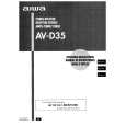 $4.99 HTD290 AIWA
Owner's Manual Complete owner's manual in digital format. The manual will be available for download as PDF file aft…
|
|
|
> |
|