|
|
|
Who's Online
There currently are 6043 guests online. |
|
Categories
|
|
Information
|
|
Featured Product
|
|
|
 |
|
|
There are currently no product reviews.
 ;
This is a good quality scan of the Operation & Maintenance (Service) Manual for the PAL version of this high-band broadcast umatic, BVU-800P
All schematics and lineup procedures appear to be included in this one manual AFAICT.
The file size is just over 113 MB which gives an idea of the quality and number of pages.
All of the schematics, which contain some fairly small print, are easily readable when you zoom into the page.
John Thompson, Newcastle Upon Tyne, England.
;
Good quality, all schematics of few of models. There is also short form of user manual and regulation manual.
;
Perfect copy of the service manual. you can enlarge every page, and it comes up
with all details.
;
It´s very very nice manual with all, what i need. Original in good quality. Very fast business. Very much thanks...
;
Purchased the manual that I was looking for at a great price and could download it easily.. Great service experience and for future purchases I plan to use the site.
Thank you very much
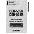
1. Focus Offset Adjustment a) Connect an oscilloscope between test points (FEl) and (VREF). b) Turn on the main power to the CD player (CD STOP). c) Adjust SFR302 so that the Offset level becomes OmV with reference to VREF. 2. Focus Bias Adjustment a) Connect an oscilloscope to test points (RFO) and (VREF). b) Insert test disc TCD�782 (YEDS-18) and PLAY BACK track No.2. c) Adjust SFl1301 so that the level of RF wave to be Maximum and clear.
3. Tracking Balance Adjustment a) Connect an oscilloscope to test points (TSO)and (VREF). b) PLAY BACK test disc TCD-782 (YEDS-18). c) With F> or<< button pressed, adjust SFR304 so that the wave form on the oscilloscope is vertically symmetrical.
A = B (OK)
I
EYE PA~ERN must be CLEAR VOLT/DIV:50mV TIME/DIv:o.5 p s
MAX 1.4*().Ivp.p
A # B (NG) VOLT/DIV:20mV TIME/DIV: 1p S DC LEVEL
Note : Test points (VREF), (FEl),( RFO),(TSO) arejumperwires are indicated on the PCB. (Refer to circuit diagram).
3
|
|
|
> |
|