|
|
|
Who's Online
There currently are 6043 guests online. |
|
Categories
|
|
Information
|
|
Featured Product
|
|
|
 |
|
|
There are currently no product reviews.
 ;
Very good manual for Technics SL 303. Manuale molto utile.
;
About one hour after checkout, the manual was available for download. Clear reading and detailed. Thanks
;
Excellent transaction - clean document received - Thanks a lot
;
Manual is in German but complete. I needed this one to fix a long lasting problem with the internal PSU of the camera. Most of the capacitors begin to leak after a few years wich results in the inability to power on the camera. When you try to turn it on the power led flickers and the unit directly turns off. Thanks to this manual I was able to locate all bad cap's and to dis- and reassemble the camera without any problems.
 ;
We received the manual in a timely manner and it was exactly what we were expecting.
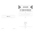
Ic DESCRIPTION-2 IC, LA9241 M
Pin No. 1 2
3
Pin Name FIN2 FIN1 E IF TB TEI TE
I/o I I I I subtracting from the F pin signal, I I I
Description Pin to which external pickup photo diode is connected. RF signal is created by adding I with the FIN1 pin signal, FE signal is created by subtracting from the FIN1 pin signal. I Pinto which external pickup photo diode is connected,
Pin No. 36 37
Pin Name TES HFL
I/o o o
Description Pin from which TES signal is output to DSP. �High Frequency Level� is used to judge whether the main beam position is on top of I bit or on top of mirror.
1
I
I
I
I
I
38
I
I
I
I
SLOF
Cv�, Cv+
I
I
I
4 5 6 7 8 9 I
I
I
I
Pin to which external pickup photo diode is connected, TE signal is created by
I
I
I I
I
Sled servo off control input pin.
I Pin to which external pickup photo diode is connected,
DC component of the TE signal is input. I Pin to which external resistor setting the TE signal gain is connected between the TE pin.
I I
39,40 41 42
I CLV error signal input pin from DSP. I RF output pin, RF gain setting and EFM signal 3T compensation constant setting pin together with 1 RFSM pin. �Slice Level Control� is the output pin which controls the RF signal data slice level by
I
RFSM RFS-
IO I 1
I I
1
I
I
o
I
TE signal output pin. TES �Track Error Sense� comparator input pin. TE signal is passed through a bandpass filter then input. Shock detection signal input pin.
I
I
43 44 45 46 47 48 49
50 51
I
I
I I
I
SLC SLI DGND FSC TBC NC DEF CLK
CL
Io I
I
I
TESI SCI
I
1 I I O
I
I DSP. Input pin which control the data slice level by the DSP. Digital system GND.
I
I Tracking gain time constant setting pin. I TA amplifier output pin. Pin to which external tracking phase compensation constants are connected between the TD and VR pins.
I I I
I I
I1I I �I
I I
I o I Output pin to which external focus search smoothing capacitor is connected.
I �Tracking Balance Control� EF balance variable range setting pin. I No connection, I Disc defect detector output pin. I Reference clock input pin. 4.23 MHz of the DSP is input.
I
I I I
I I I
12
I
TD-
I I I
I
I
I
I I
I� IO ]
I 1
-H---15 16 17
I Tracking jump signal (kick pulse) amplitude setting pin, I Tracking control signal output pin. I Focusing control signal output pin. Pin to which external focusing phase compensation constants are connected between the FD and FA pins.
Tracking phase compensation setting pin.
1 I
I I
I
Microprocessor command clock input pin.
I
I
I
I
TO FD FD-
IO IO I
52 53 54 55 56 57 58
I
DAT CE DRF FSS
VCC2
I I I I
I I
I Microprocessor command data input pin. I Microprocessor command chip enable input pin.
I
I
I
I I
I
I I
I I
o I �Detect RF� RF level detector output.
I
�
I
�Focus Search Select� focus search mode (* search/+ search) select pin. Servo system and digital system Vcc pin. Pin to which external bypass capacitor for reference voltage is connected. Reference voltage output pin.
18
FA
I
Pin to which external focusing phase compensation constants are connected between the FD� and FA� pins.
REFI VR I I I I
I
� o I I
19 20 I
FAFE I
I
Pin to which external focusing phase compensation constants are connected between the FA and FE pins.
1
I
59 60 61 62
63
LF2 PH1 BH1 LDD LDS Vccl
I Disc defect detector time constant setting pin. I Pin to which external capacitor for RF signal peak holding is connected. I Pin to which external capacitor for RF signal bottom holding is connected.
I I I I
o I FE signal output pin.
I I I I Pin to which external FE signal gain setting resistor is connected between the FE pin. Analog signal GND. No connection. � �
II
I I I
22 23
I
AGND NC
I I
o I APC circuit output pin.
I
I
I
I
I
I
APC circuit input pin.
I
I
-+-w26 27 28 29
30,31
o I Single ended output of the CV+ and CV� pin input signal.
1 I Pin to which external spindle gain setting resistor in 12 cm mode is connected.
64
I
I�
I RF system Vcc pin.
I I I
1
sPSPD SLEQ SLD
SL-, SL+
I
I
I I I
I
I
I Pin to which external spindle phase compensation constants are connected together
I with SPD pin. I Pin to which external sled phase compensation constants are connected.
o I Spindle control signal output pin.
I
I
I
o I Sled control signal output pin.
I I Sled advance signal input pin from microprocessor.
32,33 34 35
I I I
JP�, JPiTGL TOFF
1 1 I Tracking jump signal input pin from DSP.
I I I I I Tracking gain control signal input from DSP. Low gain when TGL = H. I Tracking off control signal input pin from DSP. Off when TOFF = H.
21
22
 $4.99 CSDED76 AIWA
Owner's Manual Complete owner's manual in digital format. The manual will be available for download as PDF file aft…
|
|
|
> |
|