|
|
|
Who's Online
There currently are 5422 guests online. |
|
Categories
|
|
Information
|
|
Featured Product
|
|
|
 |
|
|
There are currently no product reviews.
 ;
El manual esta muy detallado, los numeros de partes y los esquemas de despiece son correctísimos y muy claros, tanto para los técnicos experimentados como para los novatos.
 ;
Ottima qualità grafica e completo nelle notizie. Costo abbastanza contenuto.
;
Great and quick support. The maual was exactly what I was looking for and my problem
solved. Many thanks.
;
Very good service Within one day i received a pdf of the users manual and electric circuits so I was able to measure the different voltages in the printed circuit and find out the fault Payment was also reliable and easy.Without the manual i could not have repaired.So thanks to "Search for a manual"
;
you are doing great job guys.....my father ask me to find out the schematics of Sony KV25R1D to sort out the problem ..(he was electrical technician, and excperianced with TV and simillar stuff). finally he found the cause and change all necessary parts....now he has got working old dog..and is very happy!!... thank you all.. NB..he also saved the repair cost.
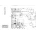
PRACTICAL SERVICE FIGURE
< TUNER SECTION >
1. FM VT Adjustment Settings : � Test point : TP2(VT) � Adjustment location : L006 Method : Set to FM 108.0MHz and adjust L006 so that the test point voltage becomes 6.0V ± 0.05V. 2. MW VT Adjustment Settings : � Test point : TP2(VT) � Adjustment location : L004 Method : Set to MW 1000kHz (U), and adjust L004 so that the test point voltage becomes 3.75V ± 0.05V. 3. FM Tracking Adjustment L005.........................................................................98.0MHz 4. MW Tracking Adjustment L003...........................................................................600kHz TC001.......................................................................1400kHz 5. AM IF Adjustment Settings : � Test point : TP1(DET) � Adjustment location : L007 Method : Adjust L007 so that the output level at 1400kHz becomes maximum.
< TUNER SECTION >
< FM SECTION >
Sensitivity: (THD 3%) Signal to Noise Ratio: (Input 60dB) Distortion: (Input 60dB) Intermediate frequency: Stereo separation: Less than 1.5% (at 98.0MHz) 10.7MHz ±0.1MHz More than 22dB Less than 19dB (88.0MHz) Less than 18dB (98.0MHz) Less than 18dB (108.0MHz) More than 60dB (at 98.0MHz)
< AM SECTION >
Sensitivity: (S/N 10dB) Distortion: (Input 74dB) Intermediate frequency: Less than 45dB (at 600kHz) Less than 45dB (at 1000kHz) Less than 45dB (at 1400kHz) Less than 1.5% 455kHz±3.5kHz
< CASSETTE SECTION >
Tape speed: Wow & flutter: S/N ratio: Distortion: Noise (PB): 3000Hz+3%-2% Less than 0.35% (JIS RMS) More than 35dB Less than 3.0% (PB) Less than 1mV (DC, MIN) Less than 1.2mV (AC, MIN) More than 45dB
< DECK SECTION >
6. Tape Speed Adjustment Settings : � Test tape : TTA�100 � Test point : J251 (PHONES jack) � Adjustment location : SFR of deck motor Method : Play back the test tape and adjust SFR so that the frequency counter reads 3000Hz ± 30Hz.
Erasing Ratio (W/O FILTER):
7. Head Azimuth Adjustment Settings : � Test tape : TTA�320 � Test point : J251 (PHONES jack) � Adjustment location : Azimuth adjustment screw Method : Play back the 8kHz signal of the test tape and adjust screw so that the output becomes maximum. 8. Bias frequncy Adjustment L801..................................................................85kHz±0.5kHz
< CD SECTION >
9. FE Balance Adjustment Settings : � Test point : IC401 PIN58 (VR), IC401 PIN 20 (FE) � Adjustment location : SFR430 Method : Playback the disc and adjust SFR430 so that the test point voltage becomes 0V.
25
 $4.99 CSDA170 AIWA
Owner's Manual Complete owner's manual in digital format. The manual will be available for download as PDF file aft…
|
|
|
> |
|