|
|
|
Who's Online
There currently are 5658 guests online. |
|
Categories
|
|
Information
|
|
Featured Product
|
|
|
 |
|
|
There are currently no product reviews.
 ;
thanks you are the best.Very good detail, Quick service response. A useful service manual with all details.
;
Great service!!! Polecam gorąco wszystkim zainteresowanym
;
I liked the price plus it had everything i needed to service the tv.
thankyou Tim Hertz
;
The manual is excellent, well detailed, and divided into two parts. Received very quickly. Thank you.
;
a solid deal - quick and without any problems.
I life in europe - with downloads no loosing time
once again
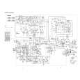
ELECTRICAL ADJUSTMENT
PRACTICAL SERVICE FIGURE
MAIN C.B
6
2
66 7 2
< TAPE RECORDER SECTION >
(ALL MODEL)
8. Tape speed Adjustment Condition: � Test tape: TTA-100 � Test point: PHONES JACK Method: � Adjustment location: SFR of deck motor Play back the test tape and adjust so that the output frequency is 3000Hz.
< RADIO SECTION >
Sensitivity: (IHF, THD 3%) (S/N 20dB) (S/N 20dB) (S/N 20dB) Intermediate frequency: FM stereo separation: FM Less than 25dB MW Less than 60dB LW Less than 66dB (200kHz) <EZ> SW Less than 40dB (8MHz) <HRJ> FM 10.7MHz AM 455kHz More than 20dB (1kHz)
EZ MODEL TC101 L102 HRJ MODEL
5
TC4 TC1 TC2 L108 Method:
9. Azimuth Adjustment Condition: � Test tape: TTA-320 � Test point: PHONES JACK � Adjustment location:Azimuth adjustment screw Play back the test tape and adjust so that the output is maximum.
< TAPE RECORDER SECTION >
Distortion: S/N ratio: Erasing ratio: Wow & Flutter: Take-Up Torque: F.F & REW Torque: Test tape: Less than 3% (PB, 1kHz) Less than 8% (REC/PB, 1kHz) More than 40dB (PB, REC/PB, AC, DC) More than 30dB Less than 0.35% (RMS) 20-60g-cm (FWD, REV) 55-120g-cm TTA-100 NORMAL TTA-602 TTA-210 TTA-257
L102 EZ MODEL
L101 TC102 L104 L109 L105 TC3
L107
L301
10. AC Bias Adjustment Condition: � Test tape: TTA-630 � Test point: TP1 � Adjustment location: L301 Method: Set up the recording mode. Adjust L301 so that the TP1 becomes 70kHz.
0
3
1
M3
4
< RADIO SECTION >
(HRJ MODEL)
1. MW/SW IF Adjustment L109 ....................................................................... 455kHz 2. MW Tracking Adjustment L101 ....................................................................... 600kHz TC4 ....................................................................... 1400kHz 3. MW Frequency Range Adjustment L104 ....................................................................... 515kHz TC102 ................................................................... 1650kHz 4. FM Tracking Adjustment L107 ........................................................................ 88MHz TC2 ........................................................................ 106MHz 5. FM Frequency Range Adjustment L108 ........................................................................ 87MHz TC1 ........................................................................ 109MHz 6. SW Tracking Adjustment L102 .......................................................................... 4MHz 7. SW Frequency Range Adjustment L105 ....................................................................... 3.8MHz TC3 ....................................................................... 12.5MHz
8
(EZ MODEL)
9
1. MW/SW IF Adjustment L109 ....................................................................... 465kHz 2. LW Tracking Adjustment L101 ....................................................................... 160kHz TC4 ......................................................................... 295kHz 3. LW Frequency Range Adjustment L104 ....................................................................... 145kHz TC102 ..................................................................... 295kHz 4. FM Tracking Adjustment L107 ........................................................................ 88MHz TC2 ........................................................................ 106MHz 5. FM Frequency Range Adjustment L108 ........................................................................ 87MHz TC1 ........................................................................ 108MHz 6. MW Tracking Adjustment L102 ....................................................................... 600kHz TC101 ................................................................... 1400kHz 7. MW Frequency Range Adjustment L105 ....................................................................... 515kHz TC3 ....................................................................... 1635kHz
13
14
|
|
|
> |
|