|
|
|
Who's Online
There currently are 5843 guests online. |
|
Categories
|
|
Information
|
|
Featured Product
|
|
|
 |
|
|
There are currently no product reviews.
 ;
Excellent printing quality.
A complete and very usefull service manual with all details.
GREAT SERVICE AT VERY LOW PRICE!
A+++++++++++++++++++++++++
;
Pioneer CDXP23S is an old model and has been top useful for me to find this Manual. CD Player is still repaired.
;
Inventory (Stock): a rather extensive list of service manuals, which are hard to find, especially 15+ yrs old.
Pricing: very reasonable.
Delivery/Response: Very Prompt delivery of product: Placed order and received download access within 1.5hrs.
Service Manual: a rather complete OEM service manual (15.5MB pdf file size). Scan quality was very good, accept for a few circuit board diagrams that were dark; Zooming, however, clarified the image. Has the required information for servicing the LD Player.
;
Perfect copy of a necessary document and my Sonic Modulator is repaired!
;
Excellent replacement for original Manual. Worth every cent ! I am totally satisfied!
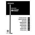
ADJUSTMENT <TUNER / FRONT>
C TUNER C.B G
9 6
CN601 FFE801
L771 TP5 (LCH)
L772
TC942 IC771 TP2 (CLK) TP6 (RCH) (DC BALANCE) TP3 TP4 (DC BALANCE)
(1/3)
TP1 (VT)
L942
L981 L941
35689
9
1
4
3
5
247
< TUNER SECTION >
1. Clock Frequency Check Settings : � Test point : TP2 (CLK) Method : Set to MW 1602kHz and check that the test point is 2052kHz ± 45Hz. 2. MW VT Check Settings : � Test point : TP1 (VT) Method : Set to MW 1602kHz and check that the test point is less than 8.0V. Then set to MW 531kHz and check that the test point is more than 0.6V. 3. MW Tracking Adjustment Settings : � Test point : TP5 (Lch), TP6 (Rch) � Adjustment location : L981 (1/3) Method : Set to MW 999kHz and adjust L981 (1/3) so that the test point becomes maximum. 4. LW VT Adjustment Settings : � Test point : TP1 (VT) � Adjustment location : L942 Method : Set to LW 144kHz and adjust L942 so that the test point becomes 1.3V ± 0.05V. Then set to LW 290kHz and check that the test point is less than 8.0V. 5. LW Tracking Adjustment Settings : � Test point : TP5 (Lch), TP6 (Rch) � Adjustment location : L941 ........................... 144kHz TC942 ......................... 290kHz Method : Set up TC942 to center before adjustment. The level at 144kHz is adjusted to MAX by L941. Then the level at 290kHz is adjusted to MAX by TC942.
6. AM IF Adjustment Settings : � Test point : TP5 (Lch), TP6 (Rch) � Adjustment location : L772 ........................... 450kHz 7. FM VT Check Settings : � Test point : TP1 (VT) Method : Set to FM 108.0MHz and check that the test point is less than 8.0V. Then set to FM 87.5MHz and check that the test point is more than 0.5V. 8. FM Tracking Check Settings : � Test point : TP5 (Lch), TP6 (Rch) Method : Set to FM 98.0MHz and check that the test point is less than 13dBµV. 9. DC Balance / Mono Distortion Adjustment Settings : � Test point : TP3, TP4 (DC balance) : TP5(Lch), TP6(Rch) (Distortion) � Adjustment location : L771 � Input level : 60dBµV Method : Set to FM 98.0MHz and adjust L771 so that the voltage between TP3 and TP4 is 0V ± 300mV. Next, check the distortion is less than 1.3 %.
� 31 �
 $4.99 AV-D37 AIWA
Owner's Manual Complete owner's manual in digital format. The manual will be available for download as PDF file aft…
|
|
|
> |
|