|
|
|
Who's Online
There currently are 6043 guests online. |
|
Categories
|
|
Information
|
|
Featured Product
|
|
|
 |
|
|
There are currently no product reviews.
 ;
I was at first dubious about payiong for downloaded manuals but having done so, I was extremely impressed with quality of the two manual I ordered, well worth the small price I paid.
I would highly recommend these to my friends.
 ;
reasonable price for the schematic - the service is perfect, all as expected and pointed by instructions - good scan of the original plans - thank you!
 ;
Manual was just as described!!! I odered it and in less than a day was able to download it and the text was clear and pages were all complete just as the original manual was. Purcashed this for a friend and they were more than happy. Perfect all around!
 ;
Excellent service and prompt delivery. But it's not a manual - only 4 pages wiring diagrams.
Thanks.
 ;
The manual I purchased was exactly what I needed to repair my Toshica television. The manual contained schematics and troubleshooting information that was very helpful.
ELECTRICAL ADJUSTMENT
PRACTICAL SERVICE FIGURE
TUNER C.B
FFE801
3
< TUNER SECTION >
<FM SECTION> Signal to noise ratio: Distortion: (Input: 60dB) Stereo separation: Intermediate frequency: More than 62dB (at 98.0MHz) Less than 2.0% (at 98.0MHz) More than 22dB (at 98.0MHz) 10.7MHz
TP5
4
L772 TP1
L771
8
TC942 IC771 L981 L942 TP2 TP3 L941 TP4 TP6
<MW SECTION> Sensitivity: (S/N 20dB) Signal to noise ratio: (Input: 74dB) Distortion: Intermediate frequency: <LW SECTION> Sensitivity:
Less than 60dB (at 600kHz) Less than 58dB (at 1000/1400kHz) More than 36dB (at 1000kHz) Less than 1.5% (at 1000kHz) 450kHz
Less than 70dB (at 144kHz) Less than 68dB (at 198kHz) Less than 66dB (at 290kHz)
7
< TUNER SECTION >
1. Clock Frequency Check Settings: Method:
4
6
7. LW Tracking Adjustment Settings: � Test point: � Adjustment location: Method: Set to LW 144kHz and adjust L941 so that the test point becomes maximum. Then set to LW 290kHz and adjust TC942 so that the test point becomes maximum.
� Test point: TP2 (CLK IC771 pin30) Set to AM 1602kHz and check that the test point becomes 2052kHz±45Hz.
2. MW VT Check Settings: � Test point: TP1 (VT) Method: Set to AM 1602kHz and check that the test point is less than 8.0V. Then set to AM 531kHz and check that the test point is more than 0.6V.
3. MW IF Adjustment Settings: � Test point: TP5, TP6 L772 .............................................. 450kHz 4. MW Tracking Adjustment Settings: � Test point: TP5, TP6 � Adjustment location: L981 (1/3) Method: Set to AM 999kHz and adjust L981 so that the test point becomes maximum. 5. FM VT Check Settings: � Test point: TP1 (VT) Method: Set to FM 87.5MHz, 108.0MHz and check that the test point is more than 0.5V (87.5MHz) and less than 8.0V (108.0MHz). 6. LW VT Adjustment Settings: � Test point: TP1 (VT) � Adjustment location: L942 Method: Set to LW 144kHz and adjust L942 so that the test point is 1.3V±0.05V. Then set to 290kHz and check that the test point is less than 8.0V.
8. DC Balance/Mono Distortion Adjustment Settings: � Test point: TP3, TP4 � Adjustment location: L771 � Input level: 60dB Method: Set to FM 98.0MHz and adjust L771 so that the voltage between TP3 and TP4 becomes 0V±0.04V. Next, check that the distortion is less than 1.3%.
35
36
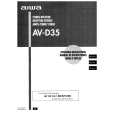
 $4.99 AVD35 AIWA
Owner's Manual Complete owner's manual in digital format. The manual will be available for download as PDF file aft…
|
|
 |
> |
|
