Shopping cart is empty
 
English Polski Spanish 
Search For a Manual
 

(e.g. AA-V20EG JVC, ZX-7 Sony )
PayPal 1000+ rating Secure, Encrypted Checkout.
 
Who's Online
There currently are 6038 guests online.
Categories
Information
Featured Product
Home >> AIWA >> ADC-EX108YZ Service Manual
 
 0 item(s) in your cart 

AIWA ADC-EX108YZ
Service Manual


Tweet about this product and get $1.00 of store credit for instant use!
  • Contains Circuit Diagrams
  • Download
  • PDF Format
  • Complete manual
  • Language: English
Price: $4.99

Description of AIWA ADC-EX108YZ Service Manual

Complete service manual in digital format (PDF File). Service manuals usually contains circuit diagrams, printed circuit boards, repair tips, wiring diagrams, block diagrams and parts list. Service Manual ( sometimes called Repair Manual ) is used mainly by technicians.

If You just want to know how to use Your tv, video, mp3 player etc. You should look for Owner's Manual. After placing order we'll send You download instructions on Your email address.

The manual is available in languages: English

Not yet ready
You must purchase it first

Customer Reviews
There are currently no product reviews.
Other Reviews
 DPSG7 KENWOOD Service Manual by Hanns Aschenneller;
Perfect copy of the service manual. you can enlarge every page, and it comes up with all details.
 BVW-300 SONY Service Manual by Marwey Butch;
It´s very very nice manual with all, what i need. Original in good quality. Very fast business. Very much thanks...
 DVL-90 PIONEER Service Manual by Fernando Rongvaux;
Purchased the manual that I was looking for at a great price and could download it easily.. Great service experience and for future purchases I plan to use the site. Thank you very much
 KR-V5080 KENWOOD Service Manual by Dave Linsell;
Exactly what was needed to assess the product - excellent value and great service
 TR-7400A KENWOOD Service Manual by David Bird;
A site where discontinualed schematic diagrams and back dated information can be found on discontinued radios tv's and any electronic equipment can be found. Newer manuals either Service and operating manuals. Radio amateurs should find this site a great source for ham radio equipment manuals. I will return to this site should I need information on any electrical equipment. priced easy to download in a PDF format and print pages need to undertake the repair.

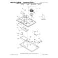
Text excerpt from page 5 (click to view)
(5)

Perform wirings to the C.Bs. Refer to Fig-5/-6; � Be sure to connect the wires coming from the P.W.B. JIG to the same connecting points on the MAIN C.B as follows. 1) Connect the motor wires and sensor (PD201) wires that are removed in step (2) to the P.W.B. JIG. 2) Connect all wires coming from the P.W.B. JIG to the respective lands of the MAIN C.B by soldering. � Connect the motor wires (BLU/WHT) of the P.W.B. JIG to the motor wire connecting lands on the MAIN C.B by soldering. � Connect the LED (LED201) wires (RED/GRY) of the P.W.B. JIG to the LED wire connecting lands on the MAIN C.B by soldering. � Connect the sensor wires (BRN/BLK) of the P.W.B. JIG to the sensor wire connecting lands on the MAIN C.B by soldering. � Connect the sensor (PS201) wires (YEL/ORG/ RED/BRN) of the P.W.B. JIG to the sensor wire connecting lands on the MAIN C.B by soldering. � Connect the SW202 wire (WHT) of the P.W.B. JIG to the SW202 wire connecting lands on the MAIN C.B by soldering. � Connect the SW203 wire (BLK) of the P.W.B. JIG to the SW203 wire connecting lands on the MAIN C.B by soldering. � Connect the SW204 wires (BLU/WHT) of the P.W.B. JIG to the leads of SW204 on the MAIN C.B by soldering. Refer to Fig-6.

Fig-5

Fig-6 (6) How to use the repair jig; When the Control Unit (CDC/CT) is going to be used. 1) After all wires and connections are complete, connect the Control Unit (CDC/CT) with the DIN jack of the P.W.B. FLEX. 2) Connect external power +12 V to ACC/BACKUP wire and ground (-) to the GROUND wire. 3) Perform the operation check. When the Control Unit (CDC/CT) is not used. 1) Connect the supplied P.W.B KEY to the MAIN C.B by performing all connections between them. Refer to Fig-7/-8. (Wires to be used for connecting the MAIN C.B are not supplied.) 2) Connect the wires as follows. Refer to Fig-9.

P.W.B KEY HOT GND

MAIN C.B TO GND

-5-

You might also want to buy

$4.99

SX-K700 TECHNICS
Owner's Manual

Complete owner's manual in digital format. The manual will be available for download as PDF file aft…

$4.99

CJ-V51 PIONEER
Service Manual

Complete service manual in digital format (PDF File). Service manuals usually contains circuit diagr…

$4.99

GRAND PRIX ELECTRONIC 754 BECKER
Service Manual

Complete service manual in digital format (PDF File). Service manuals usually contains circuit diagr…

$4.99

SX-PR602 TECHNICS
Service Manual

Complete service manual in digital format (PDF File). Service manuals usually contains circuit diagr…

$4.99

EV-S1000E SONY
Owner's Manual

Complete owner's manual in digital format. The manual will be available for download as PDF file aft…

$4.99

GRAND PRIX ELECTRONIC 780 BECKER
Service Manual

Complete service manual in digital format (PDF File). Service manuals usually contains circuit diagr…

$4.99

AG7330 PANASONIC
Service Manual

Complete service manual in digital format (PDF File). Service manuals usually contains circuit diagr…

$4.99

EVO-9850 VOLUME 1 SONY
Service Manual

Complete service manual in digital format (PDF File). Service manuals usually contains circuit diagr…
>
Parse Time: 0.973 - Number of Queries: 132 - Query Time: 0.372