|
|
|
Who's Online
There currently are 5956 guests online. |
|
Categories
|
|
Information
|
|
Featured Product
|
|
|
 |
|
|
There are currently no product reviews.
 ;
FAST very good and clear a great unexpensive job!!! very recomended for all people who are preofessional or hobbists as me!!!!!!
 ;
Thank you very much for this Service Manual, it helped us a lot to repair the M-4318!
...BUT: The parts list is missing and the free parts katalog on web isn't complete, so now we don't know the part numbers of the defect parts :(
We had to build them out of a working machine, and need the numbers to reorder the missing parts now.
;
Very good manual with clear electrical diagrams. Thanks owner-manuals.
;
Great manual, thank you, sony kp46s3 service manual perfectly, i am very happy.
;
Complete original Service Manual in good (scan) quality!
(5)
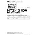
Perform wirings to the C.Bs. Refer to Fig-5/-6; � Be sure to connect the wires coming from the P.W.B. JIG to the same connecting points on the MAIN C.B as follows. 1) Connect the motor wires and sensor (PD201) wires that are removed in step (2) to the P.W.B. JIG. 2) Connect all wires coming from the P.W.B. JIG to the respective lands of the MAIN C.B by soldering. � Connect the motor wires (BLU/WHT) of the P.W.B. JIG to the motor wire connecting lands on the MAIN C.B by soldering. � Connect the LED (LED201) wires (RED/GRY) of the P.W.B. JIG to the LED wire connecting lands on the MAIN C.B by soldering. � Connect the sensor wires (BRN/BLK) of the P.W.B. JIG to the sensor wire connecting lands on the MAIN C.B by soldering. � Connect the sensor (PS201) wires (YEL/ORG/ RED/BRN) of the P.W.B. JIG to the sensor wire connecting lands on the MAIN C.B by soldering. � Connect the SW202 wire (WHT) of the P.W.B. JIG to the SW202 wire connecting lands on the MAIN C.B by soldering. � Connect the SW203 wire (BLK) of the P.W.B. JIG to the SW203 wire connecting lands on the MAIN C.B by soldering. � Connect the SW204 wires (BLU/WHT) of the P.W.B. JIG to the leads of SW204 on the MAIN C.B by soldering. Refer to Fig-6.
Fig-5
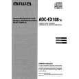
Fig-6 (6) How to use the repair jig; When the Control Unit (CDC/CT) is going to be used. 1) After all wires and connections are complete, connect the Control Unit (CDC/CT) with the DIN jack of the P.W.B. FLEX. 2) Connect external power +12 V to ACC/BACKUP wire and ground (-) to the GROUND wire. 3) Perform the operation check. When the Control Unit (CDC/CT) is not used. 1) Connect the supplied P.W.B KEY to the MAIN C.B by performing all connections between them. Refer to Fig-7/-8. (Wires to be used for connecting the MAIN C.B are not supplied.) 2) Connect the wires as follows. Refer to Fig-9.
P.W.B KEY HOT GND
MAIN C.B TO GND
-5-
|
|
|
> |
|